Cell phone:13600151511 (Manager Gao)
Cell phone:15813720327(Director Chen)
Phone:+86 0755 29832951
Office Address:East of 201, No. 20-5, Jixiang 1st Road, Pingxi Community, Pingdi Street, Longgang District, Shenzhen
Factory Address:No.2,Fudong 4th Road,Dong'ao Village,Shatian Town,Huiyang District,Huizhou City,Guangdong Province,China
At present, the thermal conductive materials used for IGBT heat dissipation are mainly thermal conductive silicone grease, and in recent years, phase change thermal conductive materials have been used for IGBT thermal conductivity. Thermal conductive silicone grease will have the problem of performance degradation after 1-2 years of use; while phase change thermal conductive materials have better durability and thermal conductivity, except for higher cost, and have greater market potential.
Figure 1 shows the schematic diagram of IG B T heat conduction. The small amount of heat exchange between the IG B T housing and the environment in the form of convection and radiation is negligible. As can be seen from the figure, the heat generated by the loss within the chip is transferred through the chip to the base of the enclosure, which in turn transfers a small amount of heat directly to the environment (in the form of convection and radiation), while most of the heat is transferred directly to the heat sink through the base via the insulating spacer and finally to the air by the heat sink.
In the heat transfer of IG B T, the main heat relies on the metal contact between the IG B T heat sink surface and the heat sink surface to transfer, and copper or aluminum is commonly used as the substrate material, whose thermal conductivity is between 2 0 0 - 3 0 0 W / (m-K). Due to the unevenness of the contact surface between the gap there is a certain air (Figure 2 a), and the thermal conductivity of air is only 0 .0 2 5 W / (m-K), and therefore seriously hinder the heat transfer; if the thermal conductivity material first coated to the IG B T surface, in the assembly and screw fastening force, squeeze out the air between the contact surface and fill the gap (Figure 2 b), the thermal conductivity of the thermal conductivity material is generally in 0 .8 - 4 W / (m-K). The thermal conductivity of the thermally conductive material is generally between 0.8 - 4 W / (m-K), and its thermal conductivity is 3 2 - 1 6 0 times higher than that of air. Although the main heat transfer is still done by the heat conduction between the metals, it can better improve the heat flow transfer between the contact surfaces, reduce the thermal resistance, and improve the heat dissipation efficiency.
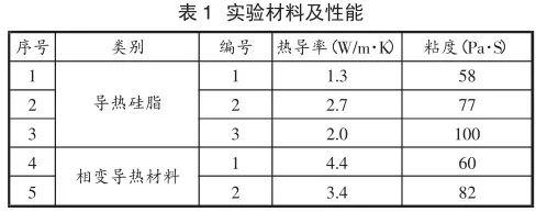
In order to compare the thermal conductivity performance between the thermally conductive silicone grease, three experimental materials are selected here for testing, and the experimental materials and performance are shown in Table 1, IG B T using Infineon F F 6 0 0 R 1 2 M E 4 A _ B 1 1 as the heat source for this test device.

The experimental scheme is to simulate the heat dissipation of IG B T under actual working conditions. This experiment provides a constant current to IG B T through DC power supply to make IG B T heat up in the open state, and the IG B T is coated with thermal conductive material and mounted on the heat sink for air-cooled heat dissipation to conduct and dissipate heat with constant power. The IG B T is regulated by current to produce different power consumption, and the tube voltage drop of the IG B T is read to calculate the current heat generation power. When the temperature equilibrium is reached, the thermal map is collected by thermal imager and analyzed and processed by corresponding software to obtain the junction temperature of IG B T chip under certain power heat conduction, and then the temperature curves under different heat generation powers are obtained to find out the difference of thermal conductivity of thermal conductivity materials. The block diagram of the test principle is shown in Fig. 3.

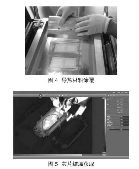
Experimental steps a . Remove and blacken the internal gel of the IG B T for the test. b . Turn on the fan, fix the air speed and record the room temperature. c . Scrub the IG B T module heat sink surface and heat sink plate surface with alcohol and evenly coat the IG B T heat sink surface with thermal conductive material using a stencil [3 - 4], the thermal conductive material is coated as shown in Figure 4. d . Install the coated IG B T onto the heatsink with IG B T screws, 1 .5 N m torque, and tighten the IG B T screws with 3 .5 N m torque after 5 m in intervals [5]. e . Turn on the IG B T by + 1 5 V gate voltage and turn on the IG B T DC power switch to set the power supply output current. f. After reaching the power balance temperature, acquire the IG B T thermal map with a thermal imager and obtain the chip junction temperature through the thermal map processing software. g. Obtain the chip junction temperature as shown in Figure 5. Measure and record the data of each group at different power levels for every 50 A DC current increase until the junction temperature of IG B T approaches 1 2 5 ℃ and stop increasing the current. h . Turn off the power, remove the IG B T , replace the thermal conductivity material to be experimented, and repeat the experimental process from step c until each material completes the experiment.

Comparison of thermal conductivity material performance
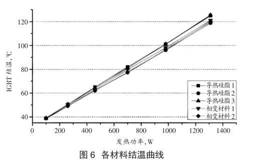
The thermal conductivity effects on the experimentally recorded junction temperature data points of IG B T at different heat generating powers were plotted and fitted to the curves, and the junction temperature curves of each material are shown in Figure 6.

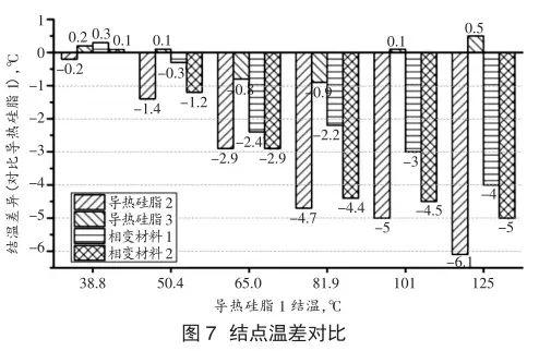
As can be seen from Figure 6, the thermal conductivity of the thermally conductive materials from high to low, i.e., the chip junction temperature from low to high, is thermal conductive silicone grease No. 2, phase change material No. 2, phase change material No. 1, thermal conductive silicone grease No. 1, and thermal conductive silicone grease No. 3. The temperature of each thermal conductive material and thermal grease 1 are compared at different heating power, and the junction temperature difference is shown in Figure 7.

The effect of coating is affected because the viscosity of the three kinds of silicone grease and two kinds of phase change thermal conductive materials used in this test are different, so the effect of removing them after coating is also different, and the effect of coating is shown in Figure 8.
As can be seen from Fig. 8, due to the high viscosity of the thermally conductive silicone grease No. 3, it not only increases the difficulty of screen printing, but also the diffusion and coverage effect of the silicone grease under the same pressure is poor, and most of the silicone grease is still in the dot state of screen coating, which cannot fill the contact surface gap better and reduces its heat dissipation effect. While the two phase change thermally conductive materials are directly wet coated with stencil tooling in the viscous state, both of them can achieve a better lamination effect.
Test results
The thermal conductivity of the thermal grease is proportional to the thermal conductivity of the thermal material under actual working conditions, and the thermal conductivity of the higher thermal grease No. 2 is significantly lower than the other two thermal greases, with a maximum temperature difference of 5.0 %.
The difference in thermal conductivity between the two phase change thermally conductive materials is also proportional to the difference in their thermal conductivity. In addition, the thermal conductivity of the phase change thermally conductive material was still better than that of the thermally conductive silicone grease No. 1 under wet coating conditions.
The thermal grease 2 exceeded the expected target and even outperformed the thermal conductivity of the two phase change thermally conductive materials due to the better applicability of the silicone grease in the screen wet coating process. For phase change thermally conductive materials, a period of preheating and sufficient compression is required to soften and fill the voids, and the advantage of phase change materials is that their thermal resistance tends to decrease as the number of cycles and working time increase.

Thermal conductive silicone grease No. 3 is not conducive to the diffusion and coverage of silicone grease due to its high viscosity, so although its material thermal conductivity is higher than that of thermal conductive silicone grease No. 1, the actual application effect does not meet the expected requirements due to the poor filling effect between the contact surfaces.
Conclusion
From the above analysis, it can be seen that for the thermal conductivity of IG B T, the thermal conductivity of the actual application is influenced by the coating effect, and a suitable viscosity can give better performance of the thermal conductivity of the thermal conductivity material; the thermal conductivity of the thermal conductivity material is also proportional to the thermal conductivity of the material itself, and the selection of a high thermal conductivity material with suitable viscosity is more beneficial to the thermal dissipation of IG B T.
Phase change thermally conductive materials have better heat dissipation effect in the experiments of actual working conditions, and their performance can be better developed by coating with wet coating process of screen, which should be expanded in the application of heat dissipation of IG B T considering its better durability.
Article loaded in Thermal Conductivity Help

- Website Home - About Us
- News - Product Show
- Honors and Qualifications - Production strength
- Case Studies - Online Message
- Contact Us
Contact Method:13600151511
Mailbox:gaowenjie@keshihua.com
Office Address:East of 201, No. 20-5, Jixiang 1st Road, Pingxi Community, Pingdi Street, Longgang District, Shenzhen
Factory Address:No.2 Fudong 4 Road, Dong'ao Village, Shatian Town, Huiyang District, Huizhou City, Guangdong Province

Follow us
